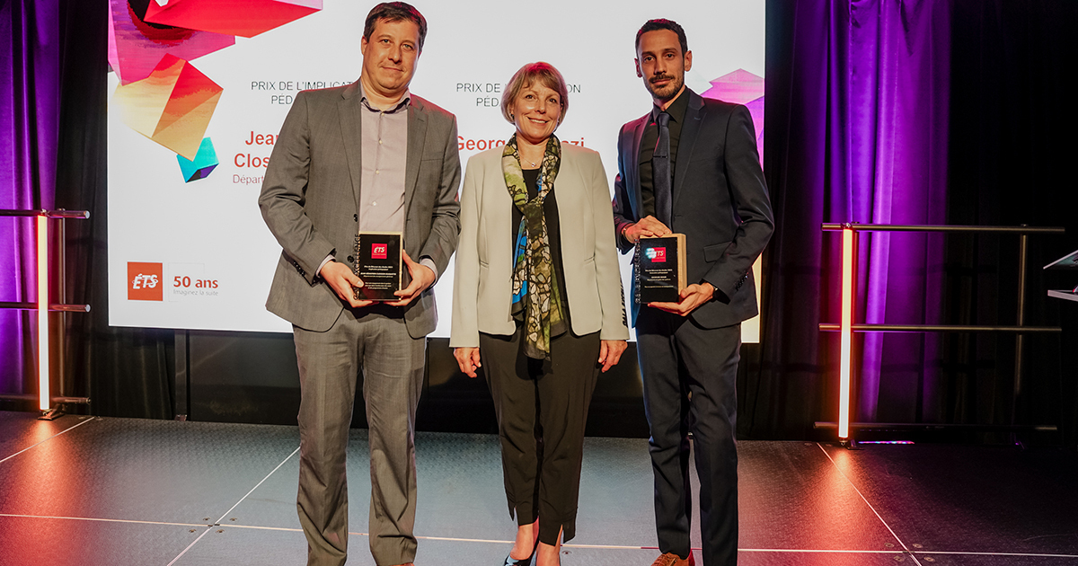
Prix et distinctions
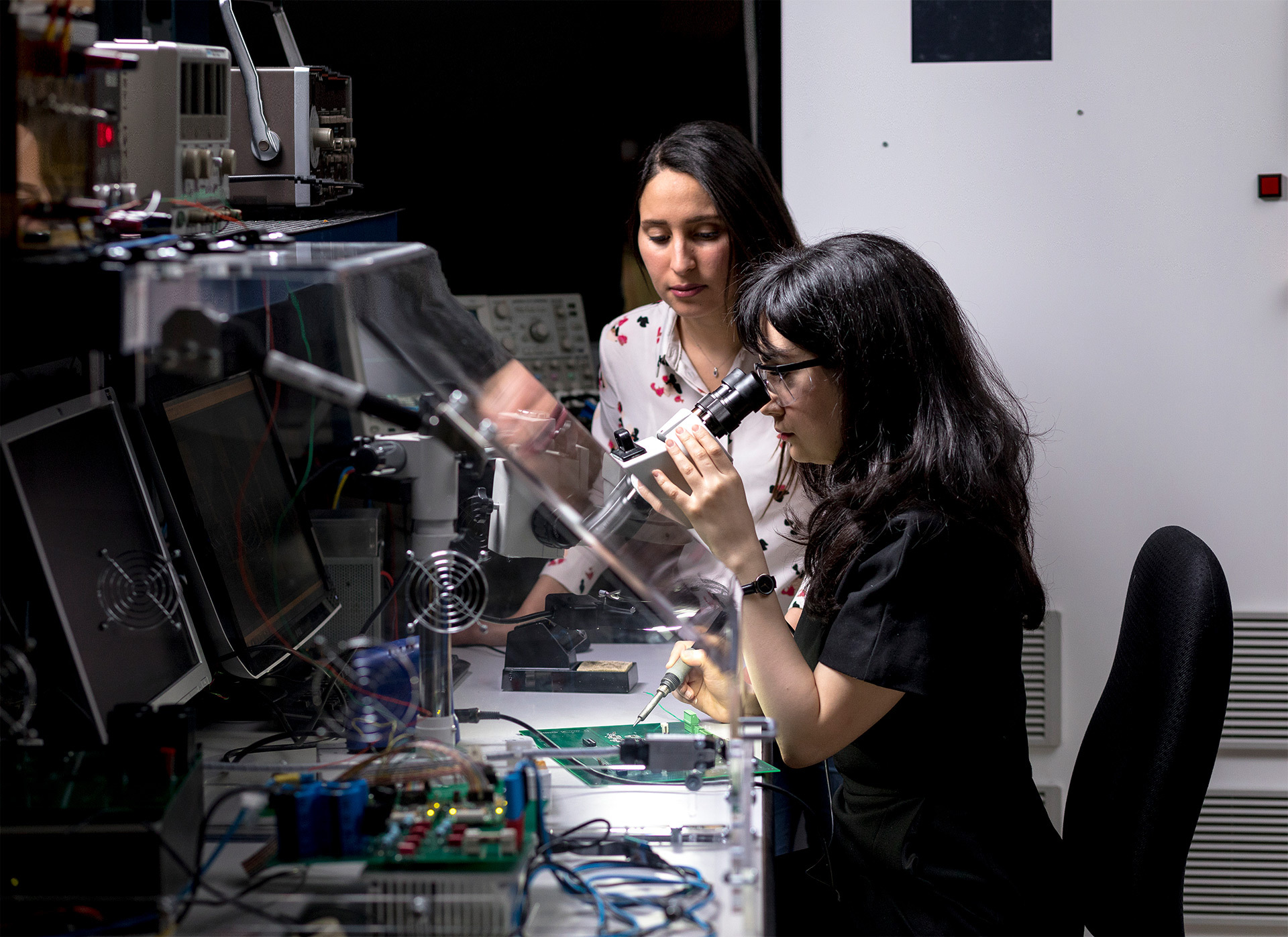
Recherche et innovation
LARCASE – Laboratoire de recherche en commande active, avionique et aéroservoélasticité
Actualités
24 avril 2024
Programme NeuroFOCUS | Brisez l’isolement, restez actives et actifs et optimisez vos capacités!


23 avril 2024
La Feuille de route gouvernementale en économie circulaire au Québec saluée par l’ÉTS, le CERIEC, l’Institut AdapT et le RRECQ

17 avril 2024
Fin de session et recherche de stage
17 avril 2024
Des investissements importants à l’ÉTS pour développer la recherche appliquée en sciences quantiques

16 avril 2024
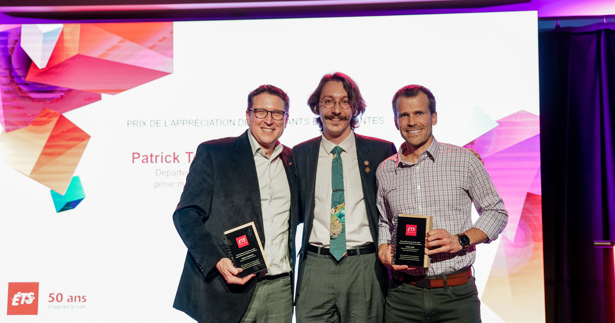
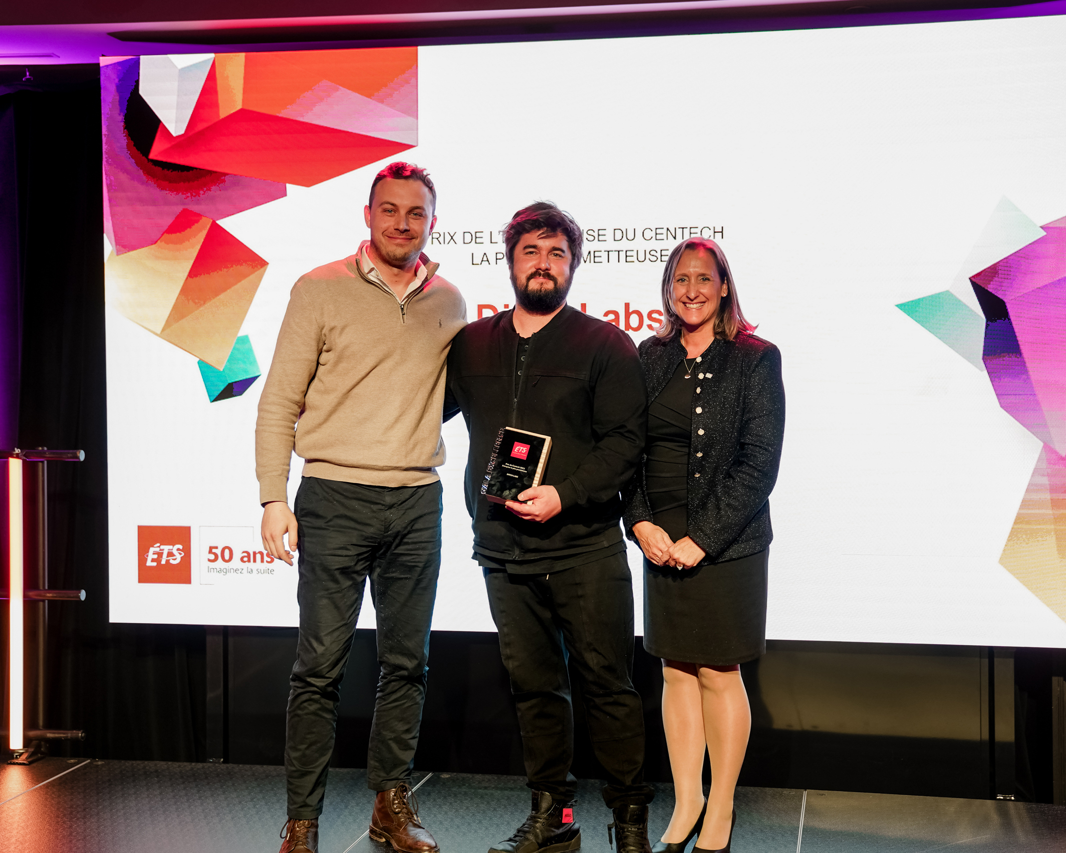
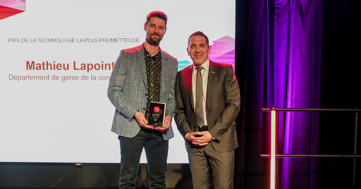
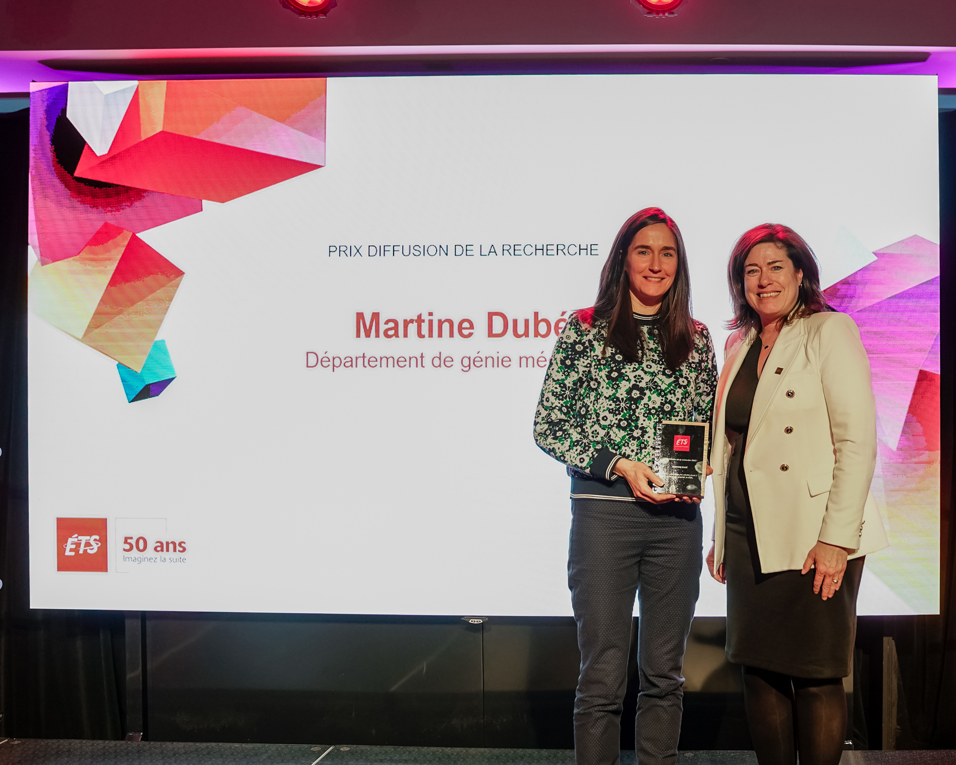
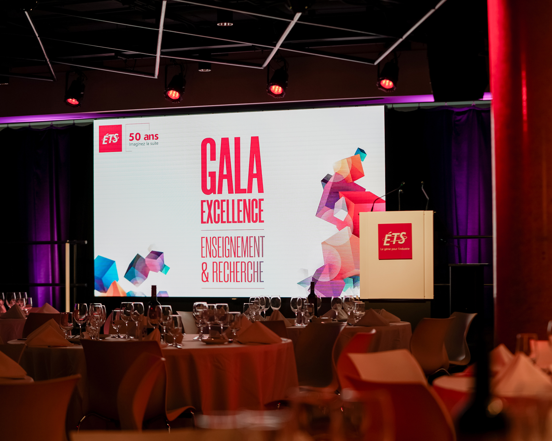
Gala d’excellence : recherche et enseignement 2024

1
Vous êtes actuellement sur cette page
2
Aller à la page : 2
3
Aller à la page : 3
...
51
Aller à la page : 51
Aller à la page suivante
Explorez votre avenir
universitaire