Designing a Drone Frame Assembly Using 3D Printing

The Dronolab student club worked with the Laboratoire sur les alliages à mémoire et les systèmes intelligents – LAMSI (Shape Memory Alloys and Intelligent Systems Laboratory) for the manufacture of their quadrirotor drone frame assembly. This article reviews the various stages of the frame assembly design. A second article, 3D Printing of a quadrotor drone frame assembly, describing the manufacturing and testing of the frame assembly, follow this article.
Foreword
Additive manufacturing (also called 3D printing) is a process used to create three-dimensional parts, layer by layer, directly from a digital model (CAD). Starting with an empty platform, the material (plastic, metal, or ceramic) is added in a controlled manner layer by layer until the final unit is formed. Using this technology, it is no longer necessary to design the unit with the subsequent assembly in mind, but rather with the way it will be functioning. In fact, this process makes it possible to consider a number of different geometries, even the most complex, and it is becoming more and more accessible to the public. With the possibility of giving certain functionalities to manufactured parts, and strengthening the structure in strategic areas, more and more people are turning to additive manufacturing of composite materials.
Issue
The Dronolab student club of the École de technologie supérieure de Montréal (ÉTS) designs drones for missions of various competitions. The drone that is currently in operation is the quadrotor type (see Figure 1). The main tasks of the drone are, among others, to gather information in the form of images that will be analyzed to map out terrain, calculate surfaces and volumes, and conduct search and rescue missions.

Figure 1 Drone from the ÉTS Dronolab student club (offered by Dronolab
The frame assembly (see Figure 2) is a main part of the drone. It supports the whole platform – arms, electronics, and payload – and is subject to significant mechanical stress. As a result, this piece is assembled with ten different parts, as it is difficult to manufacture in one step using conventional composite manufacturing methods.
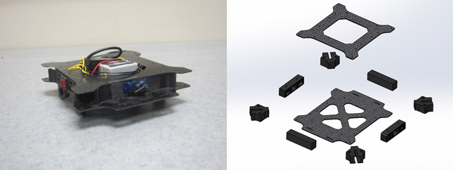
Figure 2 Figure 2 Drone frame assembly from Dronolab (offered by Dronolab
All these different parts make the assembly a long and labour-intensive process: glue and screws are needed to hold them together, which creates weakness at their interface. In addition, manufacturing these parts requires the participation of several subcontractors, thereby lengthening the production cycle. All these issues create a great need for optimization. As part of my Master’s project, the solution was the manufacture of the frame assembly in composite materials, using 3D printing.
Additive Manufacturing of Composites
The Mark One printer, developed by MarkForged, is designed to add reinforcement to the base material (matrix) with the use of two print heads. These print heads are mounted on the same linear guide, so that the motorized parts of the printer move in X or Y directions synchronously. This process combines two technologies, the Continuous Filament Fabrication (CFF), and the Fused Deposition Modeling (FDM).
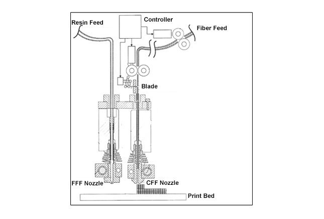
Figure 3 Schematic view of the MarkForged process (adapted with the authorization of MarkForged)
CFF technology uses material – carbon, glass, or Kevlar –in the form of a filament, and these reinforcing materials are fed through an extruder head. The extruder head guides the material, preventing its buckling, until it reaches the nozzle. The material is then heated to 260 °C and deposited on a print bed, in successive layers, forming a 3D structure. The position and orientation of the bed and the desired position of the nozzle are guided by a controller and sensors. The device also includes a blade, powered by the same controller, which cuts the filament during the layering process. The second nozzle extrudes only resin (nylon) using a conventional FDM method. Before printing, it is possible to choose the type and the filling density of the nylon (see Figures 4 A, B, C), as well as the reinforcing layers (see Figures 4 D, and E).
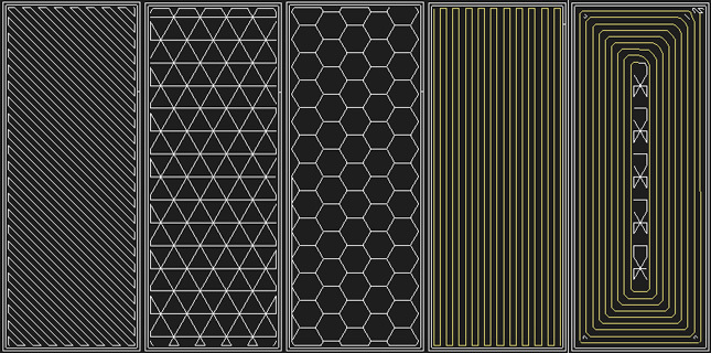
Figure 4 Filling the nylon matrix – rectangular (A), triangular (B), hexagonal (C) – and the reinforcement: – isotropic (D), and concentric (E))
Designing the Prototype
Using the 3D printing technology of the Mark One printer allows us to manufacture the frame assembly in one piece, making it much easier and quicker to mount the drone. In addition, the composite produces a quasi-isotrope piece – lightweight and reinforced in the critical areas, especially at the arm connectors, which often break. The upper and lower structures, and the arm connectors of the drone, will be reinforced with fibreglass in order to achieve a significant gain in strength. It is also possible to insert the drone control board, and subsequently weld the electronic components. This is feasible by pausing at strategic stages of the manufacturing process and manually inserting components. Note that fibreglass was chosen as the reinforcing filament material because of its high strength / pricing ratio and, the possibility to perform isotropic filling.
The unit was slightly redesigned and adapted to fit the printer – in particular the dimensions had to be reduced – but its integration into the final structure remains unchanged.
Filling the nylon was realized using a triangular pattern with a 50% density in order to ensure a good compromise between lightness, stiffness, and ease of filling. The design of the frame assembly was done using a “sandwich” arrangement simulating a composite version of an I-beam. In other words, the fibres were placed on the top (1/3 of the unit thickness) and the bottom (1/3 of the unit thickness) to maximize its strength to weight ratio, a very important feature of composite materials (see Figure 6). The reinforcing fibre forms the shell, and lightweight nylon forms the body. In this case, most of the load is supported by the reinforcement, and the core structure transfers the shear stress between the upper and lower layers.
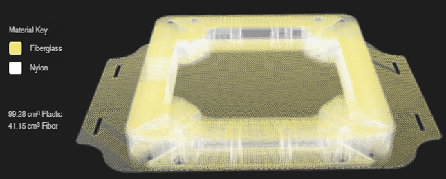
Figure 6 Internal structure modeling of the frame assembly
The orientation of the layers is determined on the base of design rules applied for laminar composites, and derived from industrial research and experience, including reflection symmetry, balancing, clustering, disorientation, the 10% rule, and damage tolerance.
To Be Continued…
A future article describing the preliminary evaluation of the prototype, its manufacturing, and its testing will follow shortly.